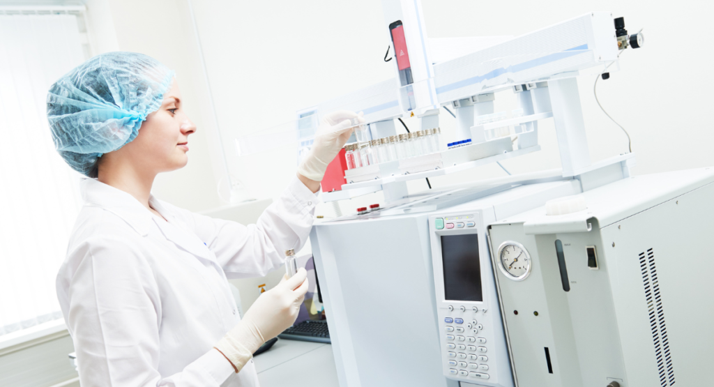
Gas Chromatography (GC) is a widely used analytical technique for separating and analysing volatile compounds in various samples. GC instruments are composed of several components, such as injectors, columns, detectors, and electronics, that work together to produce accurate and reliable results. However, like any other complex system, GC instruments can also encounter problems affecting their performance and quality.
In this article, we will discuss some of the common complaints that users of GC instruments face and provide some solutions to overcome these challenges.
Baseline related problems
One of the most common issues that GC users encounter is baseline-related problems. The baseline is the signal that the detector records when no analyte is present in the system. Ideally, the baseline should be flat and stable throughout the analysis, but sometimes it can show undesirable variations, such as drifting, rising, falling, spiking, or noise.
These variations can interfere with the peak identification and quantification and reduce the sensitivity and resolution of the analysis.
Some of the possible causes and solutions for baseline-related problems are:
Baseline drifting:
This can be caused by an accumulation of stationary phase or impurities in the column, carrier gas cylinder pressure fluctuations, or drifting carrier gas or combustion gas flows.
To solve this problem, one can trim the end section of the column, replace the carrier gas cylinder or check the gas controllers, or clean the column by heating it to its maximum temperature.
Baseline falling away slowly after a high initial value:
This can be caused by the purge valve being left closed during acquisition, inadequate purge flow rate, solvent tail peak, or pre-filters being dirty.
To solve this problem, one can alter the GC program to open the purge valve at the appropriate time, increase the purge flow rate or shorten the purge time, increase the solvent delay, or contact the service representative to replace the pre-filters.
Baseline rising:
This can be caused by an accumulation of impurities in the column or detector, column bleeding, or air leaking into the system.
To solve this problem, one can clean the column or detector by heating them to their maximum temperatures, condition or replace the column if it is excessively bleeding, or trace and repair any leaks in the system.
Baseline rising under temperature program control:
This can be caused by column contamination.
To solve this problem, one can recondition the column by heating it to its maximum temperature for a longer time.
Baseline high-standing current:
This can be caused by carrier gas flow rate being too high, column contamination or bleeding, contaminated gases, loose connections, or detector settings being too high.
To solve this problem, one can reduce the carrier gas flow rate, clean or replace the column if it is excessively contaminated or bleeding, replace the gas cylinders or filters if they are impure, tighten all connections in the system, or adjust the detector settings to lower values.
Baseline irregular shape:
S-shaped: This can be caused by excessive column bleeding during column temperature programming.
To solve this problem, one can check the tightness of the connections on the carrier gas line and install oxygen filters to prevent oxygen contamination from decomposing the stationary phase.
Baseline high-frequency noise:
This can be caused by electronic interference from external sources such as power lines, motors, pumps, fans, etc., or internal sources such as faulty cables, connectors, boards, etc.
To solve this problem, one can isolate the GC instrument from any potential sources of interference by using shielded cables and grounding wires, moving away any nearby devices that may cause interference, or contacting the service representative to check and replace any faulty components in the instrument.
Baseline spiking:
This can be caused by an electrical discharge from static electricity build-up in a dry carrier gas or sample syringe, sudden pressure changes in the carrier gas line due to valve switching, or contamination in the injector port or septum.
To solve this problem, one can humidify the carrier gas by passing it through a water bubbler or use an antistatic device on the sample syringe, use a pressure regulator to stabilize the carrier gas pressure, or clean the injector port and replace the septum regularly.
Peak related problems
Another common issue that GC users encounter is peak-related problems. A peak is the signal that is recorded by the detector when an analyte is present in the system. Ideally, the peak should be symmetrical and well-resolved from other peaks in the chromatogram.
However, sometimes peaks can show undesirable shapes or behaviours such as tailing, fronting, splitting, disappearing, or shifting. These problems can affect the accuracy and precision of the analysis and make it difficult to identify and quantify the analytes.
Some of the possible causes and solutions for peak-related problems are:
Peak tailing:
This can be caused by the injector or column being active, a flow problem, or miscellaneous factors. Injector or column activity can result from reversible adsorption of active compounds such as alcohols, amines, or thiols on the metal surfaces of the injector or column.
Flow problems can result from dead volume, obstruction, poor installation, or severe column contamination. Miscellaneous factors can include overloading of PLOT columns, co-elution, polarity mismatch between phase, solute or solvent, and some compounds always tailing.
To solve this problem, one can deactivate the injector or column by using silanizing agents or replacing them with inert ones, check and correct the flow path for any issues, or optimize the sample preparation and chromatographic conditions to avoid overloading, co-elution, or polarity mismatch.
Peak fronting:
This can be caused by overload or solubility mismatch, injector problems, or column damage. Overload or solubility mismatch can occur when the sample concentration is too high or the sample solvent is too strong for the stationary phase.
Injector problems can include poor injection technique, improper injection volume, or injector discrimination. Column damage can result from physical deformation, thermal degradation, or chemical contamination of the column.
To solve this problem, one can dilute the sample or use a weaker sample solvent, improve the injection technique or use a smaller injection volume, check and correct the injector settings to avoid discrimination or replace the damaged column.
Peak splitting:
This can be caused by injector problems, mixed sample solvent, volatility issues, or co-elution. Injector problems can include injecting the sample twice (somehow), sample degradation in the injector, or breakdown of compounds in the injector.
A mixed sample solvent can cause splitting when the sample solvent has a different polarity than the carrier gas. Volatility issues can occur when high boilers drop out on cold spots in the system. Co-elution can cause splitting when two peaks are partially resolved.
To solve this problem, one can check and correct the injection technique and settings to avoid double injection, degradation, or breakdown, use a single sample solvent that matches the carrier gas polarity, increase the transfer line temperatures and avoid any cold spots in the system, or improve the chromatographic resolution by changing the column or temperature program.
Peak disappearing:
This can be caused by the sample not being introduced or detected in the system. Sample not being introduced can result from a faulty syringe needle, clogged injector port, leaky septum, improper split ratio, etc.
Sample not being detected can result from detector malfunctioning, improper detector settings, incompatible detector type for analyte of interest, etc.
To solve this problem, one can check and replace the syringe needle if it is bent or broken, clean the injector port if it is clogged, replace the septum if it is leaky, adjust the split ratio if it is too high, check and correct the detector function and settings if they are faulty or inappropriate, or use a different detector type that is compatible with the analyte of interest.
Peak shifting:
This can be caused by leaks, column ageing, contamination or damage. Leaks can occur in any part of the system and affect the carrier gas flow rate and pressure. Column ageing can result from the gradual loss of stationary phase due to oxidation, hydrolysis, or thermal degradation.
Contamination can result from an accumulation of impurities from the sample matrix, carrier gas, or detector gases. Damage can result from physical deformation, cuts, or kinks in the column.
To solve this problem, one can trace and repair any leaks in the system, replace the column if it is aged beyond its useful life, clean the column by heating it to its maximum temperature or using a solvent flush, or replace the column if it is damaged.
Loss of resolution:
This can be caused by separation decreasing or peak broadening. Separation decreasing can result from changes in column selectivity due to aging, contamination, or damage, or changes in chromatographic conditions such as temperature program, carrier gas flow rate, or injection volume.
Peak broadening can result from extra-column effects such as dead volume, poor connections, or improper tubing dimensions, or column effects such as overloading, contamination, or damage.
To solve this problem, one can replace the column if it has lost its selectivity due to ageing, contamination, or damage, or optimize the chromatographic conditions to improve separation efficiency. One can also minimize extra-column effects by reducing dead volume, improving connections, or using proper tubing dimensions, or minimize column effects by reducing sample concentration, cleaning the column, or replacing the column if it is damaged
Detector related problems
Another common issue that GC users encounter is detector-related problems. The detector is the component that measures the amount of analyte that exits the column and generates a signal proportional to its concentration.
There are different types of detectors available for GC, such as flame ionization detectors (FID), thermal conductivity detectors (TCD), electron capture detectors (ECD), mass spectrometers (MS), etc. Each detector has its own advantages and limitations, and can also encounter some problems that affect its performance and quality.
Some of the possible causes and solutions for detector-related problems are:
Detector not responding:
This can be caused by no carrier gas flow, no detector gas flow, no power supply, no signal output, or incompatible detector type.
- No carrier gas flow can result from an empty gas cylinder, closed valve, leak, or blockage in the system.
- No detector gas flow can result from an empty gas cylinder, closed valve, leak, or blockage in the detector.
- No power supply can result from a faulty power cord, switch, fuse, or circuit board. No signal output can result from a faulty cable, connector, amplifier, or recorder.
- An incompatible detector type can result from using a detector that is not suitable for the analyte of interest.
To solve this problem, one can check and replace the gas cylinders if they are empty, open the valves if they are closed, trace and repair any leaks or blockages in the system or detector, check and replace any faulty components in the power supply or signal output, or use a different detector type that is compatible with the analyte of interest.
Detector noise:
This can be caused by electronic interference, contaminated gases, dirty or damaged detector parts, or improper detector settings. Electronic interference can result from external sources such as power lines, motors, pumps, fans, etc., or internal sources such as faulty cables, connectors, boards, etc. Contaminated gases can result from impurities in the carrier gas or detector gases that cause baseline fluctuations or spikes.
Dirty or damaged detector parts can result from an accumulation of dirt or deposits on the detector components such as jet, collector electrode, filament, ion source, etc., that cause signal instability or drift.
Improper detector settings can result from using too high or too low values for parameters such as temperature, voltage, current, gain, etc., that cause signal distortion or saturation.
To solve this problem, one can isolate the GC instrument from any potential sources of interference by using shielded cables and grounding wires, moving away any nearby devices that may cause interference, or contacting the service representative to check and replace any faulty components in the instrument. One can also replace the gas cylinders or filters if they are impure, clean or replace the detector parts if they are dirty or damaged, or adjust the detector settings to optimal values.
Detector unstable:
This can be caused by temperature fluctuations, gas flow fluctuations, or column bleed. Temperature fluctuations can result from poor temperature control, ambient temperature changes, or faulty heating elements.
Gas flow fluctuations can result from pressure regulator malfunctioning, gas controller malfunctioning, or gas cylinder pressure dropping. Column bleed can result from excessive stationary phase degradation due to oxidation, hydrolysis, or thermal degradation.
To solve this problem, one can check and correct the temperature control function, stabilize the ambient temperature, or replace the heating element if it is faulty. One can also check and correct the pressure regulator function, and the gas controller function, or replace the gas cylinder if it is low. One can also condition or replace the column if it is excessively bleeding.
Conclusion
GC instruments are powerful tools for analysing volatile compounds in various samples. However, they are also prone to problems affecting their performance and quality.
By understanding some of the common complaints that users of GC instruments face and applying some solutions to overcome these challenges, one can improve the reliability and accuracy of GC analysis and obtain better results.
If you need further support with your GC instrument then speak to one of our team today.